Engineering Resources
Looking for specific information when deciphering low-pressure sensor data? Utilize our definition of terms from A to Z.
A - D
Absolute Pressure: Pressure measured relative to a vacuum. Usually expressed in pounds per square inch absolute (psia).
Altimetric Pressure Transducer: A barometric pressure transducer used to determine altitude from the pressure altitude profile.
Auto-Referencing: A technique for eliminating errors by sampling one or more reference pressures, then correcting the output signal function.
Barometric Pressure Transducer: An absolute pressure transducer measuring the local ambient pressure.
Basic Output: The raw output of a pressure sensor that is neither amplified nor compensated by calibration.
Best Straight Line (BSL): The best straight line chosen such that the true transducer response curve contains three points of equal maximum deviation.
Burst Pressure: The maximum pressure that may be applied to the sensor without causing the sensor catastrophic failure.
Common-Mode Error: An error that is independent of the major input variable (input pressure). For All Sensors transducers, all offset errors are common-mode errors.
Common Mode Pressure: The pressure that may be applied to both sides of the diaphragm simultaneously.
Compensated Output: Output of a pressure sensor that is compensated for one or more performance parameters such as Offset, Span, Temperature effect on Offset and Span, non-linearity, Position Sensitivity, Front to Back Linearity and Warm-up shift.
Compensation of performance parameters can be achieved by design or calibration. Various compensation can be achieved by design, as an example, all A-Package products are inherently compensated for Front to Back Linearity and position sensitivity errors. Example of some parameters compensated by calibration are Offset, Span and Temperature effect on Offset and Span.
Differential Pressure: The pressure difference measured between two pressure sources. Usually expressed in pounds per square inch differential (psid). When one source is a perfect vacuum, the pressure difference is called absolute pressure. When one source is the local ambient, the pressure is called gage pressure.
Differential Pressure Transducer: A device that measures the differential pressure between two pressure sources piped to its inputs.
Digital Output: The output of a pressure sensor that is expressed in discrete quantities (quantized), generally communicated using a standard interface such as I2C or SPI. The benefit of a digital output signal is a direct interface to a host microprocessor (uP), improved noise immunity and lower component count.
E - H
Error Band: The deviation of transducer response from its BSL, defined by lines on either side of its BSL and including the maximum deviation measured for a given normal mode or common mode error.
Full-Scale: The algebraic difference between endpoints. Where one endpoint is actual offset voltage and the other endpoint is the upper limit of the range.
Full Scale Shift: The shift in sensor output voltage sensitivity to pressure over the temperature range specified. This is equivalent to temperature coefficient of sensitivity. The characteristic of this transfer curve is very close to a second order equation for the basic piezo resistive sensing element. For the millivolt output devices, this is compensated with passive resistors; and for amplified output device, it is ASIC compensated with a second order curve fit to the data taken for each part over the pressure and temperature ranges specified. The characteristic of this transfer curve does not change with any other conditions.
Gage Pressure: Pressure measured relative to ambient pressure (psig).
Hysteresis of Pressure: Pressure hysteresis is measured as the maximum difference between the output at reference conditions before and after a pressure cycle.
I - L
Interchangeability: The error band defined by the maximum signal deviation obtained when a transducer is replaced by any other transducer of the same type with equivalent pressure inputs and temperature ranges.
Linearity: The maximum deviation of measured output at constant temperature (25°C) from "best straight line" determined by three points (offset pressure, full-scale pressure, and one-half full-scale pressure) where Y= measured value for each device
Linearity, Hysteresis Error: The error in the output voltage response to pressure over the full operating pressure range relative to the ideal output voltage response; the deviation from a first order transfer curve response of output signal to pressure. This error is a function of pressure and not a function of temperature. This error is computed by measuring pressure at three pressure points; zero pressure. full scale pressure and one half full scale pressure and computed on the basis of a "best straight line" curve fit to the measured data.
M - P
Minimum/Maximum: Are the guaranteed limits for the specification. These limits are generally one hundred percent tested with a guard band between the test limits and the specification limits.
Most Probable Error: The error band obtained by computing the square root of the sum of the squares of all applicable errors specified for the transducer.
Nominal: It is the average value for a specification from product manufactured during the first production run.
Normal Mode Error: An error that is a function of (and usually assumed to be proportional to) the major input variable (input pressure). For All Sensors transducers, all span errors are normal mode errors.
Offset Calibration: The error band defined by the maximum error in calibrating the offset voltage.
Offset Error: The common-mode error band defined by the maximum deviation of offset voltage from its specified value. It may include calibration, temperature, repeatability and stability errors.
Offset Long Term Drift: The change in offset voltage that may occur over the time specified. Possible causes to this characteristic for piezo resistive pressure sensors have been studied for decades. There is, to date, no conclusive single cause or main causes to the error. Because most of All Sensors low pressure sensors use dual die electrical cross coupling compensation, there is inherent offset long term drift compensation. Products All Sensors tests for warm-up shift will generally identify any offset long term drift problems and would be rejected.
Offset Position Sensitivity: The change in offset voltage due to a change in position of the sensor. Sensors for measuring pressure exceeding 15 psi have virtually no position sensitivity. Because the diaphragm of the sensor has mass, and because the mass to diaphragm thickness ratio increases as the pressure range decreases, the sensitivity to position increases as the pressure range decreases. Because most of All Sensors low pressure sensors use dual die electrical cross coupling compensation there is inherent offset position sensitivity compensation in even the most basic sensors.
Offset Repeatability: The error band expressing the ability of the transducer to reproduce the offset voltage, measured at 25°C, after exposure to any other temperature and pressure within the specified range.
Offset Stability: The error band expressing the ability of the transducer to maintain the offset voltage with constant pressure and temperature.
Offset Temperature Coefficient: The error band defined by the maximum deviation in offset voltage as the temperature is varied from 25°C to any other temperature within the specified range.
Offset Temperature Shift: The change in output offset voltage over the specified temperature range. For non amplified sensors the specification limits are tested at three temperature points; 25°C, temperature maximum, temperature minimum, and back to 25°C. For amplified pressure sensors there are many more data points measured and the compensation is mathematically fit to the data points. There is generally no consistent equation to describe the offset temperature shift characteristic. Because most of All Sensors low pressure sensors use dual die electrical cross coupling compensation there is inherent offset temperature shift compensation in even the most basic sensor.
Offset Voltage: The output voltage when the sensor has zero differential pressure across the diaphragm. For absolute pressure sensors there is zero differential pressure across the diaphragm when the sensor is at absolute pressure of zero. For gage or differential pressure sensors there is zero differential pressure when both sides of the diaphragm are subject to the same pressure.
Offset Warm-up Shift: The change in output offset voltage that may occur when power is applied to the sensor during the first hour of operation. All Sensors tests all low pressure sensors for this parameter. Because most of the companies low pressure sensors use dual die electrical cross coupling compensation there is inherent offset warm-up shift compensation in even the most basic sensors.
Operating Range: The pressure range over which the sensor has been tested. For sensors with millivolt output this range can generally be extended to at least twice the range specified with only minor degradation to specifications. For amplified output sensors the range can be extended only ten percent before the output is "railed" to the output voltage limit.
Output Span: Is the output voltage for the specified operating pressure range. For sensors without internal voltage reference the span is ratiometric to the supply voltage of the sensor. Changes in the supply voltage to the sensor with result in a change in output span for the pressure applied. The span is the difference in output voltage at full scale pressure from the offset voltage.
Over-Pressure – Maximum: The maximum normal mode (measured) pressure that can be applied without changing the transducer's performance or accuracy beyond the specified limits. This would be applied to either port of a differential transducer. This is also called "proof pressure".
Overall Accuracy – Calibrated: The combined error band relative to the BSL with forced reference unique to one specific transducer. It excludes offset and sensitivity calibration errors. It includes all other offset and span errors: temperature, repeatability, stability, linearity and hysteresis.
Overall Accuracy – Interchangeable: The combined error band relative to an ideal transducer response characteristic. It excludes stability errors because stability error is already included in specified calibration error. It includes all other offset and span errors: calibration, temperature, repeatability, linearity and hysteresis.
Proof Pressure: is the maximum pressure that may be applied to the sensor without causing any changes in performance to the specifications.
Q - T
Reference Pressure: The pressure used as a reference in measuring transducer errors.
Reference Temperature: The temperature used as reference in measuring transducer errors.
Repeatability: The error band expressing the ability of the transducer to reproduce an output signal parameter (such as offset or span), at specified pressures and temperature, after exposure to any other pressure and temperature within the specified range.
Sensitivity: The ratio of output signal voltage change to the corresponding input pressure change. Sensitivity is determined by computing the ratio of span to the specified input pressure range.
Sensitivity Calibration: The error band defined by the maximum error in calibrating sensitivity.
Span: The arithmetic difference in transducer output signal measured at the specified minimum and maximum operating pressures.
Span Error: The normal mode error band defined by the maximum deviation of span from its specified value. It may include sensitivity calibration temperature, linearity, hysteresis, repeatability and stability deviations.
Span Repeatability: The error band expressing the ability of a transducer to reproduce its span, measured at 25°C, after exposure to any other pressure and temperature within the specified range.
Span Temperature Coefficient: The error band defined by the maximum deviation of the span as the temperature is varied from 25°C to any other temperature within the specified range.
Span Stability: The error band expressing the ability of the transducer to maintain the span voltage at any pressure within the specified range with temperature held constant.
Stability: The error band expressing the ability of a transducer to maintain the value of an output parameter (such as offset or span) with constant temperature and pressure inputs.
Supply Voltage: Power supply voltage applied at the input terminals of a pressure sensor.
Temperature Coefficient (TC): The error band resulting from maximum deviation of a transducer output parameter (such as offset or span) as temperature is varied from 25°C to any other temperature within the specified range. It is usually measured in (ppm/°C or µV/V/°C).
Temperature Compensated Output: The output of a pressure sensor that is compensated to counteract temperature dependent errors, specifically, temperature dependence of Span and Offset are compensated for.
Pressure sensor output parameters are sensitive to temperature variation, specifically, pressure response (Span) and zero differential pressure output (Offset) show temperature dependency. To counteract this temperature dependency, All Sensors provides sensor products with internal circuitry that compensates for temperature variation in Span and Offset over a specified temperature range. Temperature Compensated output products are offered in Analog (non-amplified mV, amplified 4V) and digital (SPI & I2C) outputs.
U - Z
Vacuum: A perfect vacuum is the absence of gaseous fluid.
Vacuum Range: The range of absolute pressures between a perfect vacuum (0 psia) and one standard atmosphere (14.697 psia).
Vacuum Transducer: A transducer scaled for pressure measurement in the vacuum range. This is usually an absolute transducer, but sometimes a gage transducer.
Worst-Case Error: The error band obtained by simple addition of all applicable errors specified for the transducer.

Contact our Team of Experts Today

CoBeam2 Die Technology
Die Sensing Technology
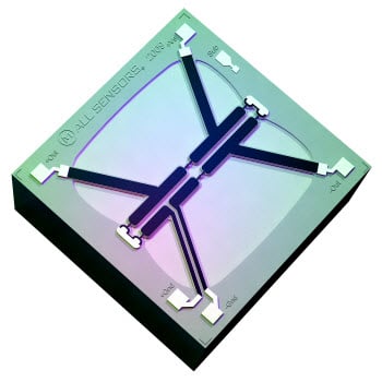
The All Sensors’ pressure sensor dies uses a proprietary Collinear Beam2 Technology registered as COBEAM² ™. This technology breakthrough advances the state of the art for piezoresistive pressure sensors beyond what has been achieved for low pressure sensing using silicon based strain technology. CoBeam2 TM Technology achieves a high level of pressure sensitivity previously requiring boss structures and larger die topologies. By eliminating the more typical boss structure in the design, both gravity and vibration sensitivity are significantly reduced. The strain sensitive resistors are processed to allow either constant current or voltage excitation through selection of temperature coefficients of resistance and sensitivity. The COBEAM² ™ Technology embodies aspects of 1950’s bonded strain gage sensors with state of the art MEMS processing of six inch silicon wafers.
Technical Data
-
.png?width=200&height=200&name=Slice%203%20(52).png)
Pressure Measurement Pressure Measurement
Download -
.png?width=200&height=200&name=Slice%203%20(52).png)
-
.png?width=200&height=200&name=Slice%203%20(52).png)
-
.png?width=200&height=200&name=Slice%203%20(52).png)
-
.png?width=200&height=200&name=Slice%203%20(52).png)
-
.png?width=200&height=200&name=Slice%203%20(52).png)
Position Sensitivity Position Sensitivity
Download -
.png?width=200&height=200&name=Slice%203%20(52).png)
-
.png?width=200&height=200&name=Slice%203%20(52).png)
-
.png?width=200&height=200&name=Slice%203%20(52).png)
-
.png?width=200&height=200&name=Slice%203%20(52).png)
Media Capability Media Capability
Download -
.png?width=200&height=200&name=Slice%203%20(52).png)
-
.png?width=200&height=200&name=Slice%203%20(52).png)
-
.png?width=200&height=200&name=Slice%203%20(52).png)
-
.png?width=200&height=200&name=Slice%203%20(52).png)
-
.png?width=200&height=200&name=Slice%203%20(52).png)
-
.png?width=200&height=200&name=Slice%203%20(52).png)
Parylene Coating Parylene Coating
Learn More


